Click on our menu buttons immediately below to find MegaSquirt® information quickly:
MicroSquirt® Module
V1/V2 MicroSquirt®
Important
Safety
Information
MicroSquirt®
Support
Forum
- MShift™ TCU
- MShift™ Intro
- GPIO Build Guide for 4L60E
- Base circuits
- GPO1, GPO2, GPO3,
GPO4 (gear LEDs)
- VB1, VB2, VB3, VB4
- PWM1, PWM2, PWM3, PWM4
- GPI1, GPI2, GPI5
(2/4WD, Input2, downshift)
- GPI3 (Temperature)
- GPI4 (Brake sense)
- EGT1, EGT2, EGT3,
EGT4 (non-CAN Load,
line pressure, Input3,
Input1)
- VR1 (Vehicle
Speed Sensor)
- VR2 (Upshift button)
- Finishing Touches
- Testing your
GPIO Board
- External Wiring Guide for 4L60E
- Current Release Code
- User Settings
- βeta Code
- Code Archives
- Purchase a
GPIO kit
- Working with the Shift Table
- Serial
Connection
Troubleshooting
- CANbus
Set-Up
- Solving VSS
Issues
- Ports, pins, circuits, connections
- MShift™ Discussion
Forums
- Misc. MShift™
Topics
- MShift™ sitemap
- Template Project Code
- GPIO Board Intro
- MShift™/GPIO
Support Forum
|

Introduction to the MicroSquirt® Module EFI controller
MicroSquirt® encapsulates pretty much everything that MegaSquirt® has to offer, in a board the size of a business card. It would be nice to have this package for a true DIY setup…
For real engine experimenters, the MicroSquirt® PCB is offered in a module format - The MicroSquirt® Module. Retailing for $249 (as of this writing), the MicroSquirt® Module is intended to be used to plugged into other boards, to let others add things like:
- USB connectivity,
- Bluetooth or Zigbee wireless,
- On-Board MAP and Baro sensors,
- On-Board stimulators for diagnostics,
- Use of Wide Band O2 sensor modules,
- Connectors for direct plug-in (EEC-IV, L-Jet, GM, etc.),
- Multiple modules for redundant setups, auxiliary fuel injectors, dual-fuel setup (gasoline+CNG), extended GPIO, etc.
There are some potential add-on circuits for the MicroSquirt® Module described here.
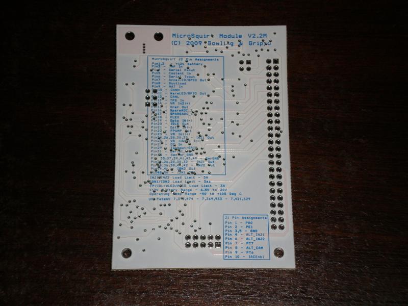
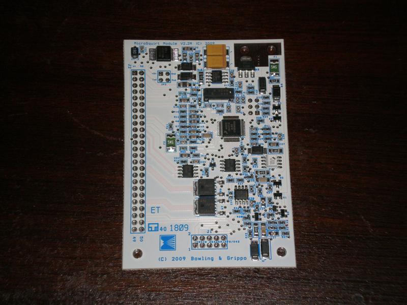
The MicroSquirt® Module has exactly same circuits as MicroSquirt® (except ignition drivers, which are logic-level output only). Module is only 2.4 inches wide by 3.5 inches long – credit-card sized! The Ampseal 35-pin connector is replaced with a 0.1” header, with two rows of 25 pins (25x2). All input and output connections are present on this header.
You can find the MicroSquirt® Module schematics here:
MicroSquirt® Module J2 25x2 Header Pin-out:
| Pin | Usage |
| 1, 2 | +12V Battery |
| 3 | MAP |
| 4 | Serial Rx |
| 5 | Coolant |
| 6 | Serial Tx |
| 7 | Accel LED/GPIO |
| 8 | Bootload |
| 9 | MAT |
| 10 | CANH |
| 11 | Warm LED/GPIO |
| 12 | CANL |
| 13 | TPS |
| 14 | VR In2(+) |
| 15 | Vref |
| 16 | Spare ADC2/MAF Pin |
| 17 | Spare ADC1 |
| 18 | Flex |
| 19 | Opto In(+) |
| 20 | FIdle |
| 21 | Opto In(-) |
| 22 | Fuel Pump |
| 23 | VR In1(+) |
| 24, 26, 28, 30, 32 | INJ1 |
| 25 | VR In (-) |
| 27 | O2 |
| 29 | Tach Out |
| 31 | Serial Ground |
| 33 | Sensor Ground |
| 35, 37, 39, 41, 43, 49 | Power Ground |
| 34, 36, 38, 40, 42 | INJ2 |
| 44, 46 | IGN2 |
| 48, 50 | IGN1 |
Example 25x2 receptacle header – Tyco/Amp 7-534206-5
Matching 25x2 pin header – Tyco/Amp 9-146254-0-25
MicroSquirt® Module J1 5x2 Header Pin-out:
Additional processor I/O brought out on J1 5x2 header (J1):
| Pin | Usage |
| 1 | PA0 |
| 2 | PE1 |
| 3, 5 | Ground |
| 4 | Alternate INJ1 |
| 6 | Alternate INJ2 |
| 7 | PT7 |
| 8 | Alternate CAM |
| 9 | PT6 |
| 10 | IAC enable |
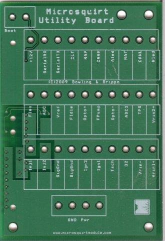
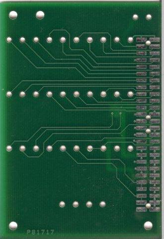
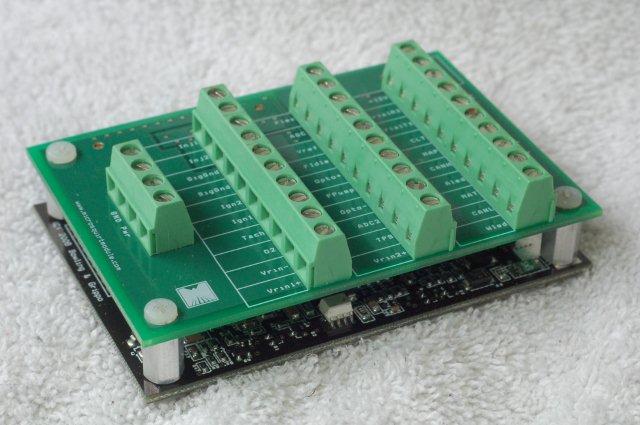
Also available for the MicroSquirt® Module is a standard adapter board, the "MicroSquirt® Utility Board" that connects the 25x2 header to terminal strips to allow a very compact, easy to connect package for the module:
This board mounts to the mounting holes in the module, using stand-offs:
Notes:
- The female 25x2 receptacle goes on the processor side of the MicroSquirt® Module (the side with all the SMT components on it).
- The header for the utility board has 26 pins (2x13 headers). To line up the pins, the extra pair of pins goes to the 'GND Pwr' 4 position terminal block/'proto' end of the board assembly, so the connections are correct and the board mounting holes line up.
MegaSquirt® and MicroSquirt® controllers are experimental devices intended for educational purposes.
MegaSquirt® and MicroSquirt® controllers are not for sale or use on pollution controlled vehicles. Check the laws that apply in your locality to determine if using a MegaSquirt® or MicroSquirt® controller is legal for your application.
©2009, 2011 Bruce Bowling and Al Grippo. All rights reserved. MegaSquirt® and MicroSquirt® are registered trademarks. This document is solely for the support of MegaSquirt® boards from Bowling and Grippo.